
One of the most common solid-state controls is known as the H-bridge. Reverse the voltage, the direction of rotation reverses. Their direction of rotation is dependant upon the polarity of the applied voltage. Permanent magnet DC motors have been around for many years and come in a variety of sizes and voltages. The other is a P-channel device rated at 55V and a RDS(on) of 0.02 Ohms max.Īlso see Test Power MOSFET Transistors, Results, Observations The IRFZ44N is an N-channel device rated at 55V and RDS(on) resistance of 0.032 Ohms max. I found two MOSFETs that work at 3.3-volts. Many micro-controllers today are using 3.3-volt Vcc. MOSFETs can be connected in parallel for high power and lower ON resistance.Īll of this is addressed in the following videos and links at the bottom of the page. The newer material addresses these issues but is still based on material below.

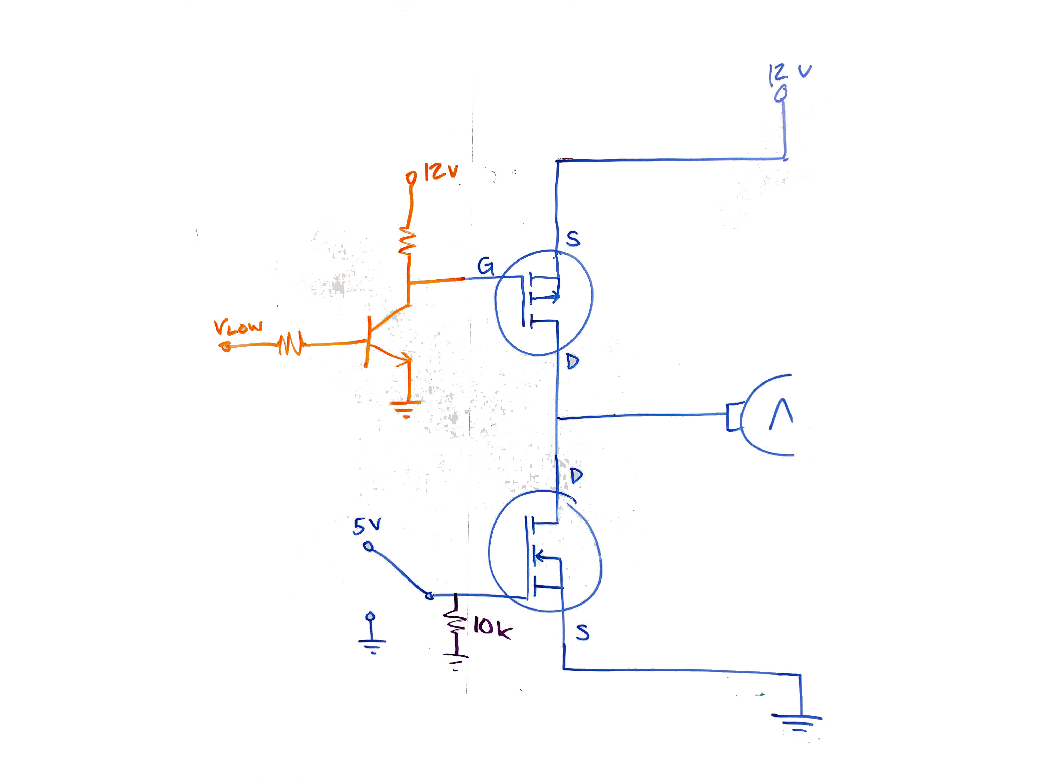
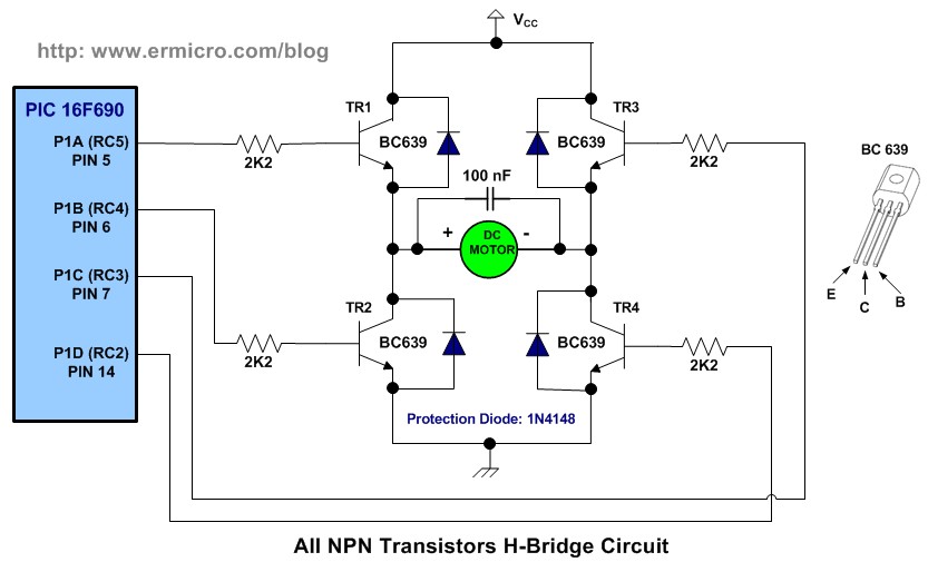
The 20-volt limit is due to the Vgs (voltage gate-source max) of the MOSFETs. Using the newer transistors the operating voltage is 5V to 20V. The information below is 100% relevant today. It is just as easy to use combinations of MOSFETs, bipolar transistors, and even insulated gate bipolar transistors. This depends on motor voltage and current that determines the H-Bridge construction. Build Power MOSFET H-Bridge for ArduinoĪny number of solid-state switches can be used for H-Bridges.Test Power MOSFET Transistors, IGBTs Results, Observations. Their low on resistance delivers more power to the motor. My recent tests have proven these devices work far better. This wastes power and the p-channel in particular runs hot. These devices are dated and have a high turn on resistance or rDS(on). I no longer recommend using IRF630 n-channel and IRF9630 p-channel MOSFETs. Which flowing of current in this form causes the motor rotated in reverse direction.Update Dec. It makes them have the current flow through Q4 go to the negative of motor and through Q2-transistors to ground. Figure 7: The motor gets the current through Q4 and Q2. The Q4 and Q2 also work by they get current from the base. Then later as Figure 7, we change power supply-V1 point into B-point. Recommended: 555 PWM LED dimmer circuit diagram Reverse Rotate control using transistor and flow through Q3 to ground successfully. Because the electrical current flowing from Q1 into the positive of the motor. So, the motor will rotate on the forward direction. Figure 6: apply power into A-point, Q1 and Q3 work. In Figure 6 circuit, if we apply power to A-point. SCR DC motor speed control circuit using IC-CMOS.Simple 12V | 9V | 6V Motor DC Speed Control with PWM mode.12V-24V PWM Motor controller circuit using TL494-IRF1405.Figure 5: we use the four transistors as a switch controller.Īnd add a diode to protect the electricity that may flow backward from the motor. Read Also: Many about transistor driver circuit s Bridge transistor Motor driverĪs Figure 5, we use the four transistors to connected into the H-bridge circuit. It causes the transistor running and the DC motor will rotate, too. When a base of transistors gets the current electricity. You see in Figure 4.įigure 4 Using the transistor as switches. We will try to use all the transistors as the switch.

As Figure 3įigure 3: Both switch-S2 and S4 are closed, causes DC motor rotates back in counter-clockwise direction.īecause that current will flow through the negative of motor cause current reversed or Rotated back counter-clockwise direction. The Motor also get current that flow through them. Reversed ModeĪnd, If both S4 and S2 are closed together. Making the DC motor rotated in features of forwarding form. As we notice that the current flowing into the positive terminal of the motor. Figure 2: the switch-S1 and S3 are closed cause the motor rotates. When having the S1-switch (closed) and S3 (closed). No the current flowing in the circuit, cause the DC motor can’t work. In-circuit, we see that all switches are the open states. Which I suggest example them as switch, so easy to understand by see its working as Figure 1.įigure 1: All the switches are OFF, causing the motor to not rotate. We can design the circuit with MOSFET or transistor to control the rotating of a motor. Often we can see this H-Bridge motor driver on many controller circuits to moving of a robot. I try to draw a circuit diagram that looks easy to see. I know you like to build a circuit project than tricky principles.


 0 kommentar(er)
